Monday, August 15, 2022

5G Node Funtional Split - gNB , AMF, SMF, UPF


 Keeping it simple for clarity of understanding.
Let's consider as two part :

Part 1: NG-RAN  -->  gNB/ng-eNB
Part2 : 5GC          --> AMF, SMF, UPF

gNB/ng-eNB Functionality:

  1. RRM - Radio Resource Magament 
  2. Radio Bearer Control
  3. Radio Admission Control 
  4. Connetion Mobility Control
  5. Dynamic Resource Allocation (Sceduling on UL and DL)
  6. IP Header Compression , Encryption and Integrity Protection of Data
  7. AMF Selection during Registration when no routing to AMF can be dterimied from the onformation provided by UE.
  8. Rounting of user plane data towards UPF
  9. Routing of Control plane Information towards AMF

AMF Functionalty:
  1. Mobility Management 
  2. Support Intra and Inter System Mobility
  3. Registraion Area Managament 
  4. Idle Mode UE Reachability
  5. SMF Selection
  6. NAS Signalling 
  7. NAS and AS Security
SMF Functionality:
  1. Session Mangement 
  2. UE IP addrress allocation and management 
  3. Downlink Data Notification
  4. Selection and Control of User Plane Function 
UPF Funtionality:
  1. Anchonr Point for Intra/Inter-RAT Mobility 
  2. SDF to QoS flow mapping
  3. Packet Routing and Forwarding
  4. Packet inspection and User plane part of policy rule enforcement
  5. Downlink packet buffering and downlink data notification triggering


Wednesday, August 10, 2022

Procedures for the 5G System : 23.502 Release 17


1. 4 --> System Procedure
a. 4.2 Connection , Registration and Mobility Management Procedures
i. 4.2.2 Registration Management procedures
1) 4.2.2.2 Registration procedures
a) 4.2.2.2.2 General Registration
b) 4.2.2.2.3 Registration with AMF re-allocation
c) 4.2.2.2.4 Registration with Onboarding SNPN 
(Standalone Non Public Network - Means Standalone Private NW)
2) 4.2.2.3 Deregistration procedures
a) 4.2.2.3.2 UE-initiated Deregistration
b) 4.2.2.3.3 Network-initiated Deregistration
ii. 4.2.3 Service Request procedures
1) 4.2.3.2 UE Triggered Service Request
2) 4.2.3.3 Network Triggered Service Request
iii. 4.2.4 UE Configuration Update
1) 4.2.4.2 UE Configuration Update procedure for access and mobility management related parameters
2) 4.2.4.3 UE Configuration Update procedure for transparent UE Policy delivery
iv. 4.2.5 Reachability procedures
v. 4.2.6 AN Release
vi. 4.2.7 N2 procedures
vii. 4.2.8 Void
viii. 4.2.8a UE Capability Match Request procedure
ix. 4.2.9 Network Slice-Specific Authentication and Authorization procedure
x. 4.2.10 N3 data transfer establishment procedure when Control Plane CIoT 5GS Optimisation is enabled
xi. 4.2.11 Network Slice Admission Control Function (NSACF) procedures
b. 4.3 Session Mangement Procedures
c. 4.4 SMF and UPF Interactions
d. 4.5 User Profile Management Procedures
e. 4.6 Security Procedures
f. 4.7 ME Identity Check Procedures
g. 4.8 RAN-CN Interactions
h. Handover Procedures
i. 4.10 NG-RAN Location reporting procedures
j. 4.11 System interworking procedures with EPC
k. 4.12 Procedures for Untrusted non-3GPP access
l. 4.12a Procedures for Trusted non-3GPP access
m. 4.12b Procedures for devices that do not support 5GC NAS over WLAN access
n. 4.13 Specific services
o. 4.14 Support for Dual Connectivity
p. 4.15 Network Exposure
q. 4.16 Procedures and flows for Policy Framework
r. 4.17 Network Function Service Framework Procedure
s. 4.18 Procedures for Management of PFDs
t. 4.19 Network Data Analytics
u. 4.20 UE Parameters Update via UDM Control Plane Procedure
v. 4.21 Secondary RAT Usage Data Reporting Procedure
w. 4.22 ATSSS Procedures
x. 4.23 Support of deployments topologies with specific SMF Service Areas
y. 4.24 Procedures for UPF Anchored Data Transport in Control Plane CIoT 5GS Optimisation
z. 4.25 Procedures for NEF based Non-IP Data Delivery
aa. 4.26 Network Function/NF Service Context Transfer Procedures
bb. 4.27 Procedures for Enhanced Coverage Restriction Control via NEF
2. 5 --> Network Function Procedure
a. 5.1 Network Function Service framework procedures
b. 5.2 Network Function services

Friday, January 8, 2021

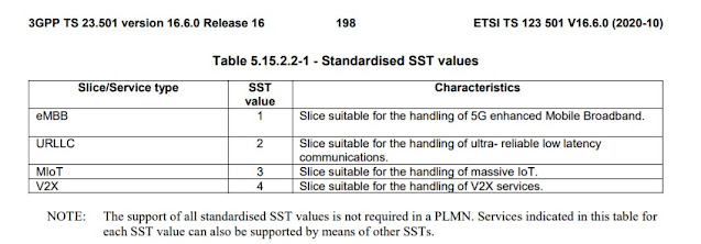
SST SD and S-NSSAI in 5G

SST - Slice/Service Type

SD - Slice Differentiator. Also referred as sst-sd in 38.331 5gnr rrc specification .
Usage: This is optional entity. This is to complement SST. Which helps to differentiate among multiple network slices.


S-NSSAI - Single Network Slice Selection Assistance Information 
Usage: In-order to identify a network slice end to end

An S-NSSAI is comprised of:


- A Slice/Service type (SST),

- A Slice Differentiator (SD), which is optional information that complements the Slice/Service type(s) to differentiate amongst multiple Network Slices.


SST is 8 bit information. SST field value can be standardized (3GPP defined 0 to 127) or non-standardized (Operator-Reserved  128 to 255).
 
SD is 24 bit information.
S-NSSAI can consit both SST and SD or only SST.
So S-NSSAI can can be of 32bit or 8 bit only.


Example of S-NSSAI inside AMF Configuration is as below

      <s_nssai>
        <id>0</id>
        <sd>198153</sd>
        <sst>3</sst>
      </s_nssai>

Where as inside CU configuration it's as below.

                   <sNSSAI>50529801</sNSSAI>

  
But if you see that number 3 , 198153 and 50529801 - it's quite difficult at first glance to relate them.
Now let's understand the relation between them.

sst is 3 here and it has 8 bit as per the structure.
So the binary format of 3 in 8 bit comes as 0000 0011 .
sd is 198153  here and it has 24 bit as per the structure.
So the binary format of 198153   in 24 bit comes as  0000 0011 0000 0110 0000 1001 .
Now if we form the s-NSSAI with available sst and sd then it becomes like below - 
8 bit sst     -  24 bit sd
0000 0011 -  0000 0011 0000 0110 0000 1001
s-NSSAI -> 0000 0011 0000 0011 0000 0110 0000 1001 -> which is in decimal 50529801.

SST value for 
eMBB - 1
URLLC - 2
MIoT - 3
V2X - 4


Source : 
23.003 : https://www.etsi.org/deliver/etsi_ts/123000_123099/123003/16.05.00_60/ts_123003v160500p.pdf
23.501 : https://www.etsi.org/deliver/etsi_ts/123500_123599/123501/16.06.00_60/ts_123501v160600p.pdf
38.331 : https://www.etsi.org/deliver/etsi_ts/138300_138399/138331/15.06.00_60/ts_138331v150600p.pdf

Monday, November 30, 2020

Radio Link Failure vs Beam Failure

This article is focused on Radio Link Failure and Beam Failure in 5G.

General Information
  • BF -  Beam Failure
  • BFD - Beam Failure Detection
  • BFI - Beam Failure Instances
  • BFR - Beam Failure Recovery
  • RLM - Radio Link Monitoring
  • RLF - Radio Link Failure
  • CFRA - Contention Free Random Access Procedure
  • CBRA - Contention Based Random Access Procedure 

General Information
  • Radio Link Failure is commonly known as RLF and an RRC Layer Procedure.
  • Beam Failure is an MAC layer Procedure
  • However both are dependent on physical layer for the indication to be received
  • BFD and Radio Link Monitoring (RLM) have some similarities but are separate UE procedures
  • Explicit configuration and implicit configuration both are possible for BFR


Thursday, October 22, 2020

Understanding RB in 5G

Let's Understand  SCS first.
As per the below table the subcarrier spacing is in the multiple of 15kHz .


Below is the NRB available as per the table provided by 3GPP Specification 38.101-2
But lets understand how to get 66RB/NRB/PRB from 100MHz with 120kHz subcarrier spacing  


To understand this we need to understand the concept of guard band.
Guard band is the spacing between two 5G band, this is to avoid interference between the band.
Below table provided by 3GPP Specification 38.101-2


The formula for calculating the guard band is as below.
Calculation for (CHBW x 1000 (kHz) - RB value x SCS x 12) / 2 - SCS/2
Now we will calculate how 66RB/NRB/PRB from 100MHz with 120kHz subcarrier spacing
As per the above calculation 
 (((100*1000) - (66*120*12))/2) - (120/2) =  (100000 - 95040)/2 -120/2 = 4960/2 - 120/2 = 2480 - 60 = 2420

2420 value is in kHz and need at the beginning and at the end of the band to guard it. 
Below table provided by 3GPP Specification 38.101-2


Now for 100 MHz in kHz is 100,000kHz
If we remove the guard band from the beginning of the band and end of the band then we get 95160kHz
100,000 kHz - 2420 kHz - 2420 kHz = 95160 kHz
Each sub carrier is of 120kHz which leads us to 793 sub carriers out of 95160 kHz 
95160 kHz /120 kHz  = 793 sub carriers
One RB consist 12 sub carrier.
so from 793 we get 793/12 = 66.083 ~ 66RB

Sunday, May 10, 2020

G's and N's in 5G

gNB, ng-eNB and en-gNB

You might come across this terms and this are utterly confusing.
Let's understand them one by one.


gNB-
gNB is the logical name for 5G radio node.
It's the pretty same as eNB in LTE.
There are various post as how the prefix arrived as 'g' here in 5G NodeB which points out towards a minutes of the RAN3#92 meeting from the year of 2016. Below are the important transcript snap from the meeting minutes.

-> Offline_46 (ZTE): – Find a proper name for “NB BS”
– various proposals, no agreement at first.
Vince Spatafora (AT&T): fNB?
Sivavakeesar Sivapathalingham (NEC): 5NB?
Sangeetha Banglae [sic] (Intel): gNB?”

Finally the award goe's to Sangeetha Bangale from Intel.
'g'  letter stands here for the generation - which interns indicates to new generation.


ng-eNB
'ng' stands for straightforward as next generation and there is no award for the guess. The 'ng' indicates a relation towards 5G. Now mind the word eNB on the second part of it. Which means this is related to LTE as well. Confusing right??
Let's make it simpler now -- This is indeed a eNB which interns uses it's conventional LTE air interface to connect with UE


en-gNB
en - stands here for enhanced. This is also similar to ng-eNB. Where instead of eB , the gNB is enhanced. Remember this is not ng-but en. Because g is already with the NB - gNB , which interns says the gNB is next generation and en indicates it is enhanced.
Which makes ir capable of talking with eNB's so that existing LTE infrastructure can be used.

gNB will be used in case of standalone 5G means in SA.
The en-gNB will be used in case of NSA/ENDC.

Tuesday, March 3, 2020

MIB SIB in 5G in General

System Information consist of MIB and number of SIB's.
System information can be devide into two group -

  1. MSI (MIB+RMSI) : Minimum System Information
    • Carries Basic information required for Initial Access
    • Information for acquiring other SI
    • MIB+RMSI
  2. RMSI : Rmenaing Minimum System Information
    • SIB1
  3. OSI: Other System Information
    • This consist of All other SIB's not broadcast-ed over Minimum SI.
    • SIB2 to SIB9


  • MIB :
    • Contains cell barred status information and essential physical layer information of the cell required to receive further system information, e.g. CORESET#0 configuration. MIB is periodically broadcast on BCH.
  • SIB1:  
    • Defines the scheduling of other system information blocks and contains information required for initial access. SIB1 is also referred to as Remaining Minimum SI (RMSI) and is periodically broadcast on DL-SCH or sent in a dedicated manner on DL-SCH to UEs in RRC_CONNECTED.
  • SIB2:
    • contains cell re-selection information, mainly related to the serving cell;
  • SIB3
    • contains information about the serving frequency and intra-frequency neighbouring cells relevant for cell re-selection (including cell re-selection parameters common for a frequency as well as cell specific reselection parameters);
  • SIB4
    • contains information about other NR frequencies and inter-frequency neighbouring cells relevant for cell re-selection (including cell re-selection parameters common for a frequency as well as cell specific reselection parameters);
  • SIB5:
    • contains information about E-UTRA frequencies and E-UTRA neighbouring cells relevant for cell reselection (including cell re-selection parameters common for a frequency as well as cell specific re-selection parameters);
  • SIB6:
    •  contains an ETWS primary notification;
  • SIB7:
    •  contains an ETWS secondary notification;
  • SIB8:
    •  contains a CMAS warning notification;
  • SIB9:
    •  contains information related to GPS time and Coordinated Universal Time (UTC).


5G Node Funtional Split - gNB , AMF, SMF, UPF

 Keeping it simple for clarity of understanding. Let's consider as two part : Part 1: NG-RAN  -->  gNB/ng-eNB Part2 : 5GC          --...